
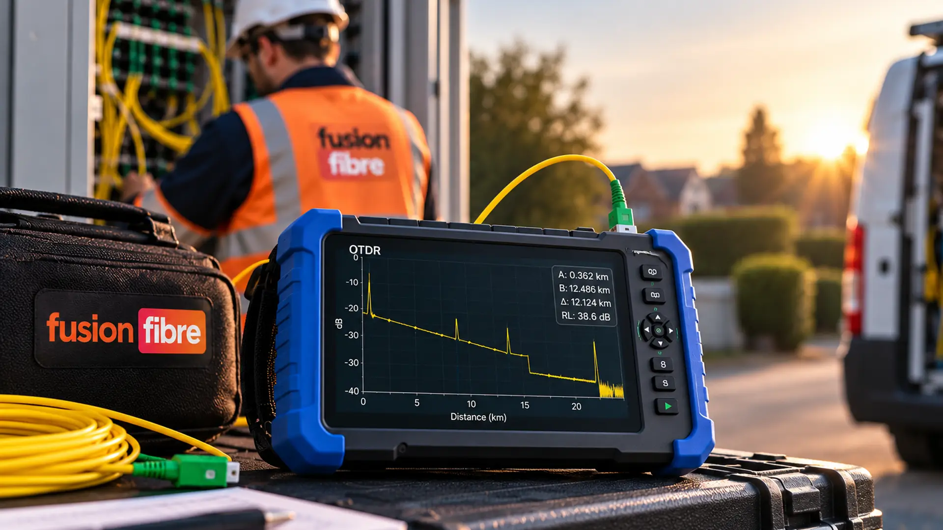
If you install, maintain or troubleshoot fibre optic networks, knowing where a problem is can save a lot of time.
An OTDR (Optical Time Domain Reflectometer) helps you do exactly that.
It sends pulses of light through an optical fibre and analyses the light that returns, building a picture of what's happening along the fibre and where.
This can help you locate fibre breaks, investigate excessive loss, check splices and connectors, measure fibre length and assess the condition of an installed link.
The challenge is knowing what the results are telling you. An OTDR trace can look pretty cryptic if you haven't worked with one before.
In this guide, we'll explain how an OTDR works, what it measures, how to read an OTDR trace and what can affect your results.
What is an OTDR?
OTDR stands for Optical Time Domain Reflectometer.
It's a fibre optic test instrument used to understand what's happening along the length of an optical fibre.
Unlike a basic loss measurement, which tells you how much signal has been lost between two points, an OTDR can help show where individual events and losses occur along the fibre.
Depending on the fibre, equipment and test setup, an OTDR can help you identify:
- Fibre length
- Attenuation
- Splice and connector loss
- Reflective events
- Bends and other sources of loss
- Fibre breaks
- The approximate distance to a fault
The results are typically displayed as an OTDR trace – a graph showing how the returned optical signal changes over distance.
This is especially useful when troubleshooting. If a fibre link has excessive loss, knowing there's a problem is only half the job.
An OTDR can help you narrow down where along the fibre that problem is occurring.
How does an OTDR work?
An OTDR sends a pulse of light into an optical fibre and measures the light that returns to the instrument.
As light travels through the fibre, a small amount is scattered back towards the OTDR. This is known as Rayleigh backscatter.
Changes in the returned signal allow the instrument to build a picture of the fibre's characteristics over its length.
Some components or discontinuities can also produce stronger reflections.
Connectors, for example, can create a reflective event that looks very different on a trace from a fusion splice.
Because the OTDR knows when the light pulse was transmitted and measures how long the returned light takes to arrive, it can calculate the distance to events along the fibre.
The basic process is:
OTDR sends light → light travels through the fibre → some light returns → OTDR measures the return → software creates a trace
The instrument repeats this process many times and averages the measurements to improve the resulting trace.
What does an OTDR measure?
An OTDR can provide several useful measurements from a fibre link.
Distance
The OTDR uses the travel time of the light to calculate the distance to events along the fibre.
This is one of its most useful troubleshooting capabilities.
If a fibre has been damaged somewhere between two locations, an OTDR can help estimate the distance from the test point to the fault.
Engineers can then narrow down the section of cable that needs investigating rather than searching the entire route.
Fibre Attenuation
Optical fibre loses a small amount of signal as light travels through it. An OTDR can measure the attenuation of the fibre, commonly expressed in dB/km.
A consistent downward slope on the trace generally represents the normal attenuation of the fibre.
An unexpected change in that slope may warrant further investigation.
Event Loss
An OTDR can estimate the loss associated with individual events along the fibre.
These might include:
- Fusion splices
- Mechanical splices
- Connectors
- Bends
- Other localised losses
This can help identify events that are contributing more loss than expected.
Reflectance
Some events reflect light towards the OTDR.
Reflectance measurements help indicate how strongly an event reflects light.
Connectors and open fibre ends are common examples of reflective events.
What is an OTDR Used for?
OTDRs are used throughout the installation and working life of fibre optic networks.
Fibre Installation and Commissioning
Once fibre has been installed, OTDR testing can help verify the condition of the link and document the location and characteristics of events along it.
Saving these results also provides a useful reference for future maintenance.
If a problem develops later, engineers can compare a new trace with the original commissioning trace and investigate what has changed.
Locating Fibre Faults
A failed fibre link doesn't necessarily tell you where the problem is.
An OTDR can help identify the distance to a break or other significant event, making it easier to narrow down the physical location of the fault.
This is particularly useful on longer cable routes where inspecting all the nooks and crannies of the installation would be impractical.
Checking Splices
Fusion splices should introduce very little loss when completed correctly.
OTDR testing can help identify the location of splices and estimate their loss, making unusually lossy events easier to spot.
Investigating Connectors
Connectors can introduce both loss and reflection.
An OTDR trace can help engineers identify connector locations and investigate events that appear abnormal.
Physical inspection and cleaning are still important.
Contaminated fibre connectors are a common source of optical problems, so suitable inspection and cleaning procedures should form part of fibre troubleshooting.
Fibre Maintenance
OTDR traces can provide a useful record of a fibre link's condition.
Comparing traces taken at different times can help identify changes in the network and support preventative maintenance and fault investigation.
What Does an OTDR Trace Show?
An OTDR trace plots the returned optical signal against distance.
At first glance, it can look like a sloping line interrupted by peaks, drops and steps.
Those shapes contain useful information.
A typical trace may include:
- The OTDR connection and launch section
- The fibre's normal attenuation
- Connector events
- Splice events
- Bends or other localised losses
- The end of the fibre
Learning to recognise these patterns is an important part of OTDR testing.
How to Read an OTDR Trace
You don't need to interpret every point on a trace manually.
Modern OTDRs can identify and classify many events automatically.
Understanding what the trace represents is still valuable, particularly when troubleshooting unusual results.
The Downward Slope
A healthy length of fibre usually appears as a gradually descending line.
That decline represents attenuation as the optical signal travels along the fibre.
A Sudden Step Down
A drop without a large reflective peak can indicate a non-reflective loss event.
A fusion splice is a common example.
A bend may also produce additional loss, although comparing measurements at different wavelengths can help with identifying bend-related events.
A Sharp Peak
A strong upward spike usually indicates a reflective event.
Potential causes include connectors, mechanical connections and an open fibre end.
The shape and size of the event, along with its position in the link, help determine what it represents.
A Sudden End to the Trace
A significant reflection followed by the disappearance of the normal fibre backscatter may indicate the end of the fibre.
An unexpected end earlier than the known cable length could indicate a break.
Reflective and Non-Reflective OTDR Events
One of the useful distinctions when interpreting an OTDR trace is whether an event is reflective or non-reflective.
Reflective Events
Reflective events send a noticeable amount of light back towards the OTDR.
They may be associated with:
- Connectors
- Mechanical splices
- Open fibre ends
- Fibre breaks with reflective interfaces
On the trace, these commonly appear as spikes.
Non-Reflective Events
Non-reflective events cause loss without producing the same pronounced reflection.
Fusion splices are a typical example.
They tend to appear as a step down in the trace rather than a large peak.
Understanding this difference can help narrow down what you're looking at when an unexpected event appears.
What are OTDR Dead Zones?
After a strong reflection, the OTDR detector needs time to recover before it can accurately distinguish another event.
The section affected by this is known as a dead zone.
Two types are commonly discussed.
Event Dead Zone
The event dead zone relates to the minimum distance required for the OTDR to distinguish between closely spaced reflective events.
Attenuation Dead Zone
The attenuation dead zone is the distance required after a reflective event before the OTDR can return to the backscatter level accurately enough to measure another event's loss.
Dead zones matter because fibre links often contain events relatively close together, particularly near the beginning and end of the link.
This is one reason launch and receive fibres can be useful.
Why Use an OTDR Launch Cable?
Connecting an OTDR directly to the fibre under test can make it difficult to characterise the first connector properly because it sits within or close to the OTDR's initial dead zone.
A launch cable places a known length of fibre between the OTDR and the link being tested.
This moves the first connection of the link further away from the instrument, allowing the OTDR trace to settle before reaching it.
A receive cable, sometimes called a tail cable, can be connected at the far end of the link.
Using both can help characterise the connections at each end of the fibre.
The required launch and receive fibre lengths depend on factors such as the OTDR, pulse width and fibre link being tested, so the appropriate test procedure and instrument guidance should be followed.
How to Use an OTDR
Exact procedures vary between instruments, networks and test requirements, but a typical OTDR test follows a few core steps.
1. Inspect and Clean the Connectors
Before connecting test equipment, inspect the fibre interfaces using appropriate equipment and clean them where required.
A contaminated connector can affect the measurement and may transfer contamination to another interface.
2. Connect the Launch Fibre
Connect a suitable launch cable between the OTDR and the fibre under test where required.
Make sure the launch fibre matches the fibre type you're testing.
3. Configure the OTDR
Depending on the instrument, settings may include:
- Test wavelength
- Distance range
- Pulse width
- Averaging time
- Index of refraction
- Event thresholds
Many OTDRs provide automatic test modes that select suitable settings, which can be helpful for routine testing.
Manual settings provide greater control when investigating a particular issue or working with more demanding links.
4. Run the Test
Start the measurement and allow the OTDR to collect and average the returned signal.
Longer averaging can improve trace quality, although it also increases test time.
5. Review the Trace and Event Table
Check the overall trace as well as the instrument's automatically detected events.
Look for unexpected:
- Loss
- Reflections
- Splices
- Bends
- Breaks
- Fibre ends
Automatic event analysis is useful, but it shouldn't replace understanding the trace when a result looks unusual.
6. Save the Results
Saving traces provides evidence of the test and creates a reference that can be useful during future troubleshooting.
Depending on the OTDR and workflow, results may also be exported for reporting and certification records.
Choosing the Right OTDR Wavelength
Common OTDR wavelengths for singlemode fibre include 1310 nm and 1550 nm, while multimode testing commonly uses 850 nm and 1300 nm.
Testing at more than one wavelength can reveal useful information because the fibre and certain faults behave differently depending on wavelength.
For example, bending loss is generally more pronounced at longer wavelengths.
Comparing traces can therefore help identify possible macro-bends that may be less obvious at another wavelength.
The correct wavelength should be selected according to the fibre type, network and applicable testing requirements.
OTDR Pulse Width Explained
Pulse width affects how much optical energy the OTDR sends into the fibre during each pulse.
A longer pulse can provide greater measurement range and help the OTDR see further along a long or lossy link.
There is a trade-off.
Longer pulses generally reduce the instrument's ability to distinguish events that are close together and increase dead zones.
Shorter pulses provide better spatial resolution but have less energy, which can limit measurement range.
Choosing a pulse width therefore depends on what you're trying to measure.
For a short link containing closely spaced events, a shorter pulse may be preferable. For a much longer fibre route, a longer pulse may be required to achieve sufficient dynamic range.
OTDR Dynamic Range
Dynamic range helps describe an OTDR's ability to measure longer fibres and links with greater loss.
An OTDR with greater dynamic range can generally measure further into a fibre link before the backscatter signal becomes too weak to distinguish reliably from noise.
More isn't automatically necessary.
The appropriate dynamic range depends on the length and loss characteristics of the networks you're testing.
An instrument intended for shorter enterprise links may have very different requirements from one used on long-distance telecoms infrastructure.
OTDR vs Optical Power Meter: What's the Difference?
An OTDR and an optical loss test setup answer different questions.
An OTDR provides information about the fibre over distance. It can help locate and characterise individual events.
An optical power meter and light source can be used to measure end-to-end insertion loss.
Put simply:
OTDR: Where is the loss occurring?
Light source and power meter: How much total insertion loss does the link have?
Depending on the applicable standard, network and acceptance requirements, both types of testing may be needed.
An OTDR shouldn't automatically be treated as a replacement for end-to-end loss measurement.
Common OTDR Testing Mistakes
Even a capable OTDR can produce misleading results if the test setup isn't right.
Testing Through Dirty Connectors
Always inspect and clean fibre interfaces as appropriate before testing. Contamination can affect results and potentially damage or contaminate other interfaces.
Using the Wrong Fibre Type
Launch cables and other test components should be suitable for the fibre under test.
Mixing inappropriate fibre types can introduce measurement errors.
Using an Unsuitable Pulse Width
A very long pulse may hide closely spaced events inside dead zones.
A very short pulse may not provide enough dynamic range for a long link.
Relying Entirely on Automatic Settings
Automatic modes make OTDR testing considerably easier and are useful for many everyday measurements.
When troubleshooting a difficult link, understanding and adjusting the test parameters can provide a clearer picture.
Ignoring the Launch Fibre
Without sufficient launch fibre, accurately characterising the first connection can be difficult.
Looking Only at the Event Table
Event tables make results easier to interpret, but the underlying trace can reveal details that automated analysis may classify incorrectly or that deserve closer inspection.
Use both.
Can an OTDR Locate a Fibre Break?
Yes. Fault location is one of the key reasons OTDRs are used for fibre troubleshooting.
If a fibre breaks, the OTDR trace can show where the normal backscatter signal ends.
The instrument can then calculate the approximate distance from the test point to the event.
That doesn't necessarily translate directly into a physical point on a building or street.
Cable routing matters. A fibre measured as 800 metres long may travel through ducts, chambers, cabinets and spare cable loops before reaching the fault.
Accurate network records therefore make OTDR distance measurements much more useful.
Can an OTDR Test Live Fibre?
This depends on the equipment, wavelength, network and test method.
Connecting test equipment to an active fibre without understanding the network can interfere with services or expose the OTDR detector to optical signals it wasn't intended to receive.
Some instruments and testing methods are specifically designed to support testing on certain live networks, including approaches using filtered ports and out-of-band wavelengths.
Check the network design and OTDR manufacturer's guidance before testing an active fibre.
How Accurate is an OTDR?
OTDR accuracy depends on more than the specification printed on the instrument.
Factors that can influence measurements include:
- OTDR configuration
- Index of refraction settings
- Pulse width
- Wavelength
- Fibre characteristics
- Connector condition
- Launch and receive fibres
- Signal-to-noise ratio
- Event type
- Averaging time
It's also worth distinguishing between distance accuracy and loss measurement accuracy. They describe different aspects of the test.
For reliable results, use suitable test procedures, understand the instrument's limitations and configure it for the fibre link you're measuring.
Do You Need an OTDR for Fibre Optic Testing?
It depends on what you need to find out.
If you only need to know the end-to-end insertion loss of a fibre link, other fibre test equipment may be more appropriate.
If you need to know where events are located, investigate a break, assess individual splices or build a detailed picture of a fibre over distance, an OTDR becomes far more useful.
For installers and engineers working across larger or more complex fibre networks, it can turn a vague "there's a problem somewhere on this link" into a much more targeted investigation.
Choosing an OTDR
There isn't one OTDR specification that suits every fibre network.
Before choosing an instrument, consider:
- Singlemode, multimode or both
- Required test wavelengths
- Typical fibre lengths
- Required dynamic range
- Event and attenuation dead zones
- Measurement accuracy
- Automatic event analysis
- Touchscreen and interface usability
- Result storage and reporting
- Connectivity and data transfer
- Battery life
- Launch cable requirements
- Applicable testing standards
Start with the networks you expect to test rather than buying solely around the largest headline specification.
A contractor working primarily on relatively short LAN fibre links may have different requirements from an engineer maintaining long-distance singlemode networks.
OTDR FAQs
What Does OTDR Stand For?
OTDR stands for Optical Time Domain Reflectometer. It is an instrument used to analyse optical fibre over distance.
What Does an OTDR Do?
An OTDR sends light pulses through a fibre and analyses returned light to identify events and measure characteristics such as distance, attenuation, loss and reflectance.
What Can an OTDR Find?
Depending on the link and test conditions, an OTDR can help identify connectors, splices, bends, excessive loss, reflective events, fibre ends and breaks.
What is an OTDR Trace?
An OTDR trace is a graphical representation of the returned optical signal over distance. Engineers use the shape of the trace and detected events to understand what is happening along the fibre.
Can an OTDR Measure Fibre Length?
Yes. An OTDR calculates distance using the time taken for light to travel through the fibre and return to the instrument.
Can an OTDR Find a Fibre Break?
Yes. An OTDR can identify the distance to an event that may represent a fibre break, helping engineers narrow down where to investigate.
Why Do You Need a Launch Cable with an OTDR?
A launch cable places a length of fibre between the OTDR and the link under test. This helps move the first connection beyond the instrument's initial dead zone so it can be characterised more effectively.
What Wavelengths are Used for OTDR Testing?
Common wavelengths include 850 nm and 1300 nm for multimode fibre and 1310 nm and 1550 nm for singlemode fibre. Other wavelengths are also used for particular applications.
Is an OTDR the Same as a Fibre Optic Tester?
An OTDR is a type of fibre optic test instrument, but "fibre optic tester" covers a much broader range of equipment. Optical power meters, light sources, visual fault locators, inspection equipment and other instruments perform different testing and troubleshooting jobs.
Getting More from OTDR Testing
An OTDR gives engineers something particularly valuable when working with fibre: visibility over distance.
It can show where connections, splices and loss events occur, help locate breaks and provide a trace that can be saved for future comparison.
Getting useful results still depends on good testing practice.
Clean connections, appropriate launch fibres, suitable test settings and an understanding of the trace all matter.
Choose the OTDR and test method around the fibre network you're working on, and you'll have far more useful information when it comes to commissioning links, finding faults and keeping fibre infrastructure performing as expected.
